Safety of IPS System
- Structural Analysis
-
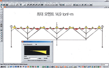
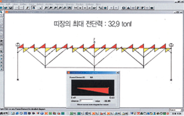
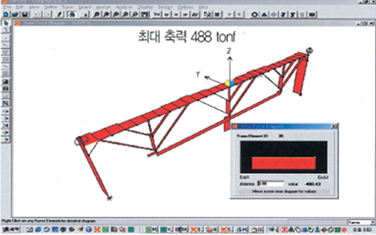
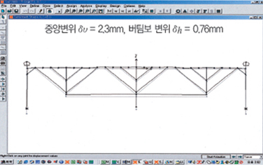
Based on a structural analysis of 32m long IPS wale, the max, moment and the max, Shear force depend on the distance between support beams, and they are decreased by 95%, which is almost no moment and no shear are found in the IPS system. The IPS wale should be a double wale for supporting 488ton. The max, displacement in center is 2.3mm.
- Safety Analysis
-
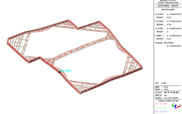
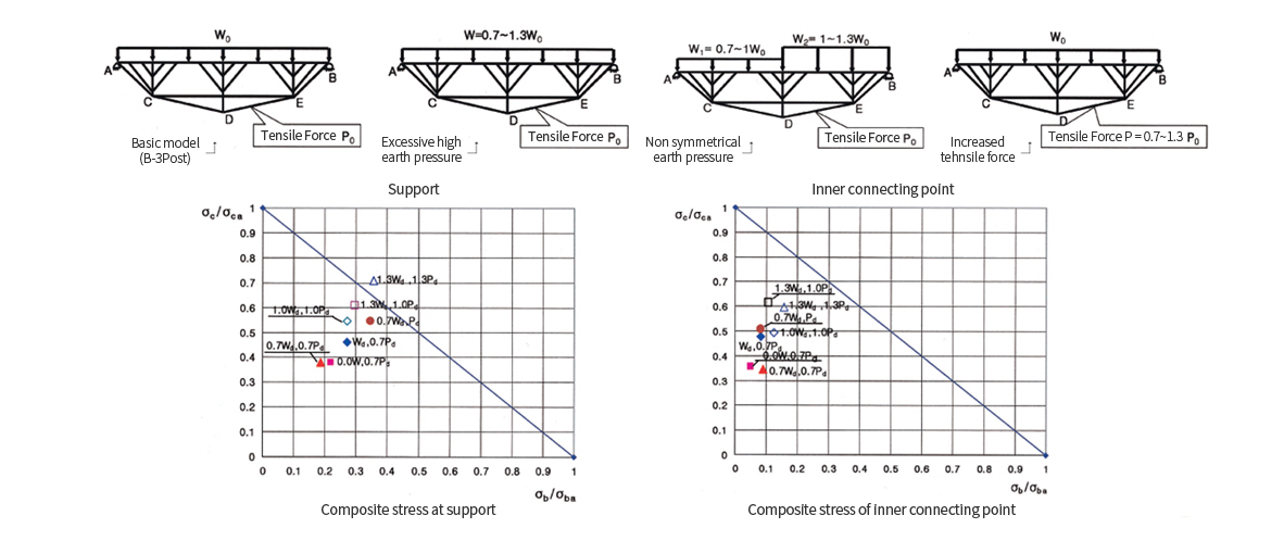
The safety of IPS system has been analyzed for abnormal cases such as excessive high earth pressure, uneven earth pressure of PC tendon failure. Most of the cases are turned out to be safe except for one case, when both the earth pressure and the tension of PC tendon increases by 30%.
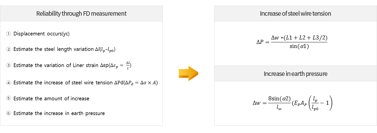
Safety verification by measuring FD
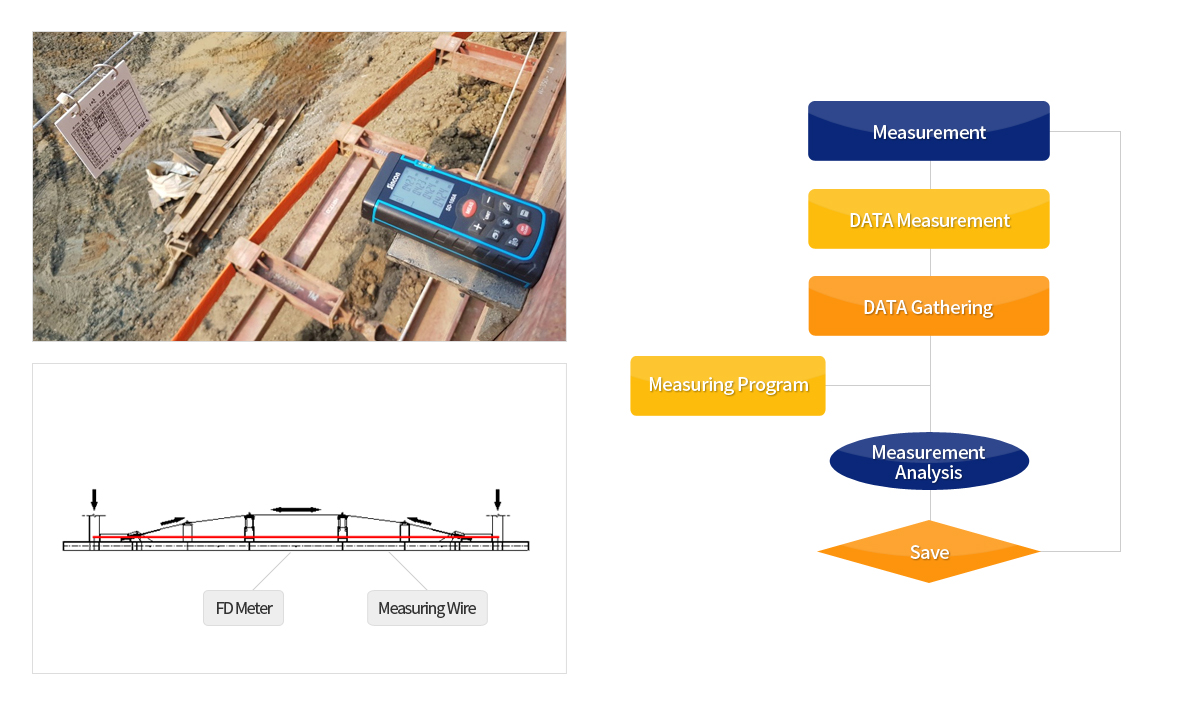
Standard table of FD Detection
(Unit: mm)
| NO. | Accumulate Displacement | Countermeasure | Excavation Criteria | Note |
|---|---|---|---|---|
| Excavation Depth | ||||
| 1 | 15 ~ 30 | 10 | H / 500 | Safe |
| 2 | 30 ~ 50 | 30 | H / 300 | Attention |
| 3 | 50 ~ | 50 | H / 200 | Danger |
| Measuring Point | Anchor and Center of IPS wale |
|---|---|
| Measurement Method | Laser distance measuring device |
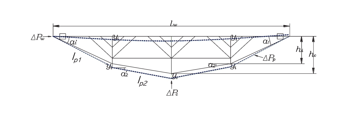
| Principle | Measured deflection of IPS wale predicts the forces of soil pressure, Wale and strut forces and tendon tension. |
Deformation and stiffness of IPS stripe according to ground load change
Ensuring the safety of IPS based on the destruction progress
- The strut is designed to be stronger than the IPS wrist strap.
- The initial tension of the belt is 70% of the design load.
- If the earth pressure exceeds 70% of the design load, the band zone begins to deform toward the excavation field.
- Step pressure and corresponding method are shown in the table below.
| Soil Pressure
(% of Design Value) |
Countermeasure | Deformation(mm) | Stage | Measuring(times/week) | |
|---|---|---|---|---|---|
| 1st step | 70% | - Increase prestressing force from 70% to 100% | Under 10mm | safe | 1 |
| 2nd step | 70% | - Increase prestressing force up to 100% of design value to meet excessive soil pressure | 10~30 | attention | 2 |
| 3rd step | 100% | - Wale or Strut Reinforcement - Increase prestressing force of tendon |
30~50 | alert | 3 |
| 4th step | 130% | - Install additional tendon - Install interlayer strut and wale |
Above 50mm | danger | everyday |
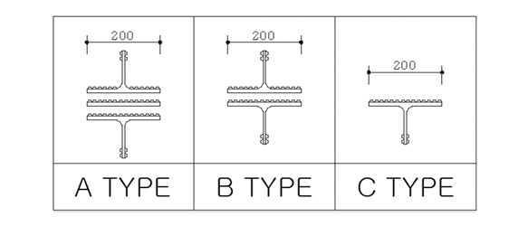
Grooving: Transferring lateral loads to the wall
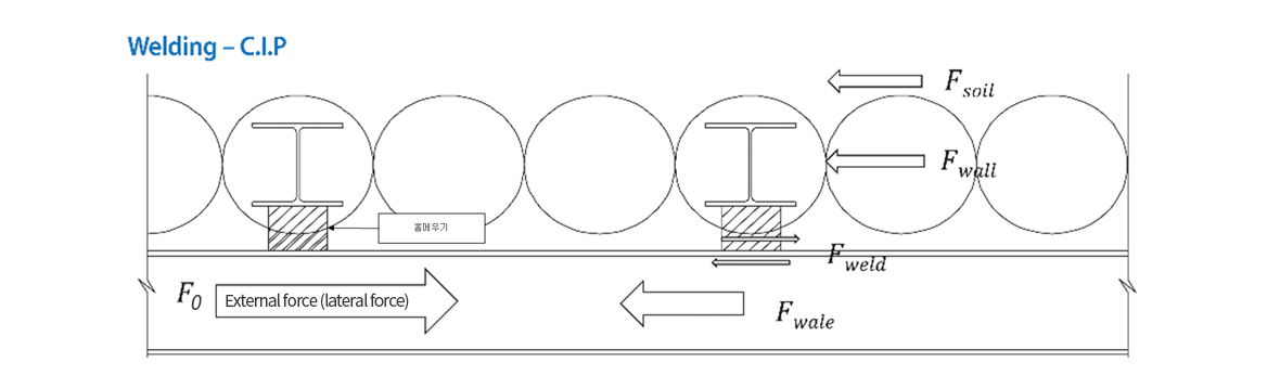
- ※ Resistance to lateral forces F0 = Fwale + Fweld
-
※ The sum of the lateral resistance of the CIP(Fwall) and Skin Friction(Fsoil) of CIP and Soil is equal to the shear force generated in the grooved weld(Fweld).
| Welding TYPE | Permissible welding steel (ton/ea) | |
| Weight | 6mm | 10mm |
| A | 84 ton | 141 ton |
| B | 56 ton | 94 ton |
| C | 28 ton | 47 ton |